


 English
 中文简体
Author: WeiBo
Date: Oct 26, 2026
Chemical Injection System Calibration and Testing in Plastic Processing Lines
Content
- 1 What Chemical Injection System Calibration and Testing Really Cover
- 2 Why Screw and Barrel Condition Changes the Calibration Baseline
- 3 A Practical Calibration and Testing Workflow for Process Engineers
- 4 Test Methods That Reveal More Than a Single Flow Reading
- 5 Tolerance, Frequency, and Records: Setting Realistic Standards
- 6 Common Calibration Failures and How to Catch Them Early
- 7 Selecting a Screw and Barrel Supplier for Stable Injection Performance
- 8 FAQ: Chemical Injection System Calibration and Testing
- 8.1 How often should a chemical injection system be calibrated?
- 8.2 What tolerance is reasonable for chemical injection system calibration?
- 8.3 Should calibration be done with water or with the production chemical?
- 8.4 What tests should be repeated after replacing a screw or barrel?
- 8.5 How can I tell whether the dosing error comes from the pump or the screw and barrel?
- 8.6 Does a bimetallic screw barrel eliminate calibration problems?
- 8.7 Why does additive dosing drift after a material lot change?
- 9 Final Commissioning Checklist for Stable Additive Injection
A glass-filled polypropylene job is running on an injection molding machine. The additive feeder is set to deliver 2.4% masterbatch, the screw speed looks normal, and the operator has not touched the dosing pump since the last maintenance stop. Yet the batch is showing color streaks, occasional short shots, and a rising reject rate. The immediate suspicion is usually the feeder. Often, however, the real issue is that chemical injection system calibration and testing has been treated as a one-time setup task rather than a chain of checks that includes the dosing device, the melt-delivery hardware, and the process conditions around them.
The conclusion first: calibration is not simply adjusting a pump until the output number looks acceptable. In plastic processing, a reliable chemical injection system depends on a stable melt path through the screw and barrel, repeatable pressure and temperature, and a dosing response that is verified at more than one rate. Testing should confirm what the system does after warm-up, after a rate change, after a material change, and after maintenance. If those four conditions are not covered, a calibration sheet can look perfect while production still drifts.
That matters for injection molders, extrusion lines, and equipment builders because additive injection is rarely isolated from the rest of the machine. Colorants, stabilizers, foaming agents, processing aids, and reactive components all enter a melt stream that is being conveyed, compressed, sheared, and metered by a screw and barrel. The calibration baseline is therefore only as stable as the mechanical platform underneath it.
Calibration proves the dosing device; testing proves whether the whole injection and melt-delivery system can hold that performance in production.
What Chemical Injection System Calibration and Testing Really Cover
A common mistake is to separate “the pump” from “the machine.” On a production line, the chemical injection system includes the supply tank, suction line, pump or feeder, discharge line, check valves, pressure gauges, control signal, injection point, and the screw-barrel assembly that receives the additive. A calibration error can originate in any of those areas. A peristaltic or diaphragm pump may be mechanically sound but draw air through a worn seal. A loss-in-weight feeder may be accurate in isolation but deliver unevenly if the barrel pressure fluctuates. A gear pump may hold a steady output at one speed but lose repeatability during turndown.
It helps to divide calibration and testing into three layers. The first is the instrument layer: setpoint, sensor feedback, stroke length, pulse frequency, weight reading, and control response. The second is the hydraulic or mechanical layer: seals, valves, lines, screws, barrels, check rings, nozzles, and drive components. The third is the process layer: melt temperature, back pressure, residence time, material viscosity, and the actual point where the additive meets the polymer. A useful test plan touches all three, because a fault in one layer often disguises itself as a fault in another.
| Layer | What to verify | Practical test | Effect on additive injection |
|---|---|---|---|
| Instrument and control | Setpoint accuracy, signal scaling, response time, alarm limits | Step-change test at low, middle, and high rates | Reveals delayed response, wrong scaling, or unstable feedback |
| Mechanical delivery | Pump seals, check valves, line restrictions, air ingress, screw and barrel wear | Visual inspection, pressure hold test, gravimetric output check | Explains drift, pulsation, intermittent under-dosing, or repeatability loss |
| Melt and process | Barrel temperature profile, back pressure, screw speed, residence time, injection point condition | Short-run production trial with pressure and temperature logging | Shows whether the additive is being delivered into a stable melt stream |
| Documentation | Baseline output, correction factors, maintenance history, material batch | Before-and-after records with pass/fail limits | Prevents repeated adjustments from becoming the new normal |
The table is deliberately practical rather than theoretical. In a busy plant, the person calibrating the system may be a technician, a process engineer, or a maintenance lead. The test should be simple enough to repeat, but specific enough to expose a trend. A single output reading at one setpoint is useful for a quick check, but it does not tell you whether the system responds correctly when production moves to a different rate or material.
For injection molding and extrusion alike, the best starting point is a written calibration boundary. Define which components are in scope, which readings are recorded, and which conditions invalidate a test. For example, a test performed before the barrel reaches thermal equilibrium may not represent production. A test performed with a different chemical viscosity than the production fluid may produce a correction factor that is misleading. A test that ignores screw wear may pass the pump but fail the product.
A calibration record is only meaningful when it states the machine condition, material condition, and test rate under which the reading was taken.
Why Screw and Barrel Condition Changes the Calibration Baseline
Chemical injection is often judged by the dosing device alone, but the receiving system has a major influence on what “accurate” means in production. The screw and barrel set the pressure profile, conveying stability, shear history, and melt uniformity. If the screw has wear at the flight tips, if the barrel bore has lost tolerance, or if the check ring on an injection unit does not seal consistently, the additive may be correctly metered at the pump and poorly distributed at the melt stream. The operator then adjusts the pump to compensate for a mechanical problem, which pushes the calibration away from its true baseline.
Consider an injection molding machine running a shear-sensitive additive. A worn non-return valve can allow slight backflow during injection. The dosing pump may still deliver the programmed shot, but the actual amount of additive reaching the mold can vary from cycle to cycle. A pressure-hold test alone may not catch this because the leak is small and intermittent. A step-rate test combined with a shot-weight check and a barrel-pressure trace is more revealing. The same logic applies to extrusion: a worn metering section can produce pressure pulsation that makes a liquid additive appear to “surge” even when the pump is steady.
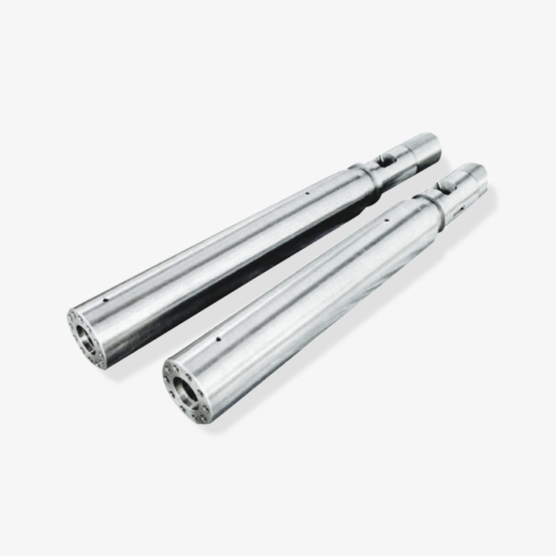
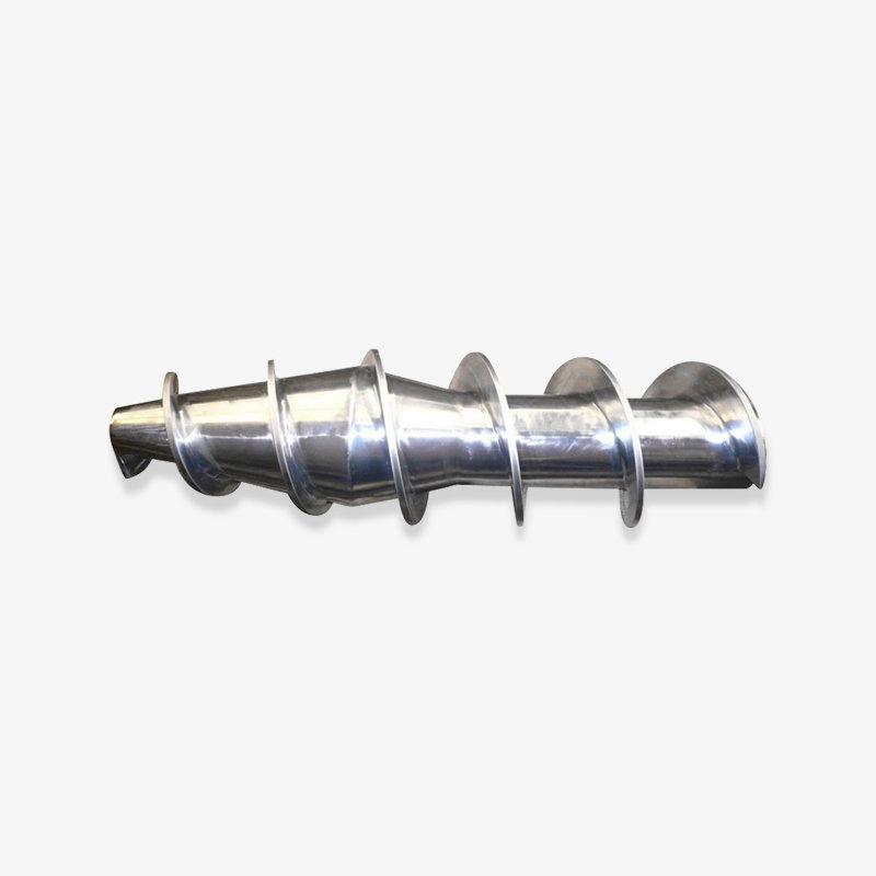
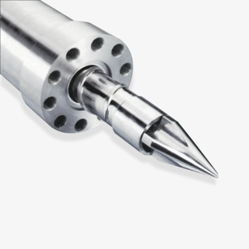 Custom Injection Molding Screw and BarrelCustom screw and barrel for injection molding, with matched clearance to support stable material transport and reduce fluctuations; relevant when assessing replacement hardware and calibration.View Product →
This is why a screw and barrel supplier should be treated as part of the calibration conversation, not just a spare-parts source. Dimensional consistency, material selection, and surface condition affect how quickly a machine returns to a stable baseline after maintenance. When a replacement screw or barrel is installed, the chemical injection system should be re-tested rather than assumed to be unchanged. The new hardware may alter pressure response, residence time, and mixing behavior enough to require a new correction factor.
Aggressive additives and filled compounds make the wear question more important. Glass fibers, mineral fillers, and some flame retardants can accelerate clearance growth in the barrel and on the screw. A bimetallic barrel or specially hardened screw may improve wear resistance, but it does not remove the need for calibration. It simply gives the calibration a better chance of remaining stable between maintenance intervals. The wrong conclusion is “upgrade the metallurgy and forget the test plan.” The better conclusion is “upgrade the wear resistance and use the test plan to verify that the improvement holds.”
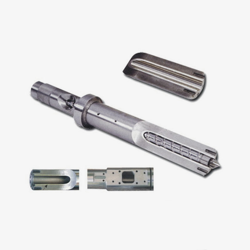
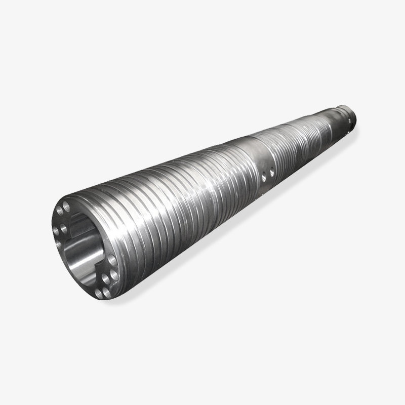
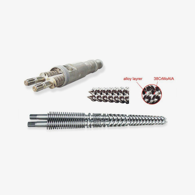 Custom Bimetallic Screw Barrel for Special PlasticsBimetallic screw barrel with dual-alloy structure and wear-resistant coating for engineering and special plastics; a candidate when comparing wear-resistant replacement options and inspection records.View Product →
For processors comparing replacement options, ask for inspection records that connect to the calibration plan: screw diameter, flight geometry, barrel bore, surface hardness, and straightness. These details matter because a chemical injection system that is calibrated on a worn machine may require continuous correction, while the same system on a mechanically sound machine can hold a stable setpoint with far fewer adjustments. The goal is not a perfect machine; the goal is a known machine condition that the calibration is based on.
If the screw and barrel are worn, the dosing pump may be blamed for a pressure and mixing problem that calibration alone cannot correct.
A Practical Calibration and Testing Workflow for Process Engineers
The following workflow is designed for a plastic-processing plant where a chemical additive, colorant, foaming agent, or processing aid is injected into an extruder or injection molding machine. It is not a substitute for the equipment manufacturer’s instructions, but it gives a repeatable sequence that can be adapted to different pump types and feeder designs.
- Define the production condition. Record the material grade, additive type, target dose, melt temperature profile, screw speed, back pressure, cycle time, and line rate. Calibration without these conditions is only a workshop exercise.
- Inspect before adjusting. Check tanks, filters, suction lines, seals, check valves, injection points, and the barrel area around the feed throat and nozzle. Look for leaks, crystallized chemical, blocked lines, air ingress, and worn connections. A small leak on the suction side can cause erratic dosing that looks like a control problem.
- Confirm thermal stability. Bring the barrel and dosing lines to production temperature and allow enough soak time. Viscosity changes with temperature, so a calibration performed too early may not hold after the machine stabilizes. For temperature-sensitive chemicals, verify that the injection line is not overheating or cooling unevenly.
- Establish a reference output. Run the dosing device at a known rate and collect output by weight or volume over a fixed time. Use clean containers and a scale or gauge suitable for the target dose. Record the actual output, not the displayed setpoint. Repeat at least twice to see repeatability.
- Test at multiple rates. Check low, middle, and high production rates. A pump that is accurate at 70% stroke may drift at 20% stroke. A feeder that performs well at steady speed may respond poorly to short cycle demands. The purpose is to find the range where the system holds tolerance, not to force one correction factor across the entire range.
- Verify response time. Introduce a setpoint change and measure how long the system takes to reach the new output and stabilize. This is especially important on injection molding machines with short cycles and on extrusion lines where additive changes affect color or foaming quickly. Slow response can lead to over-correction by the operator.
- Run a production trial. Produce a short run under normal conditions and check the result: color, density, foaming structure, strength, surface finish, or whatever the additive is intended to control. If the additive is critical to dimensional stability or regulatory compliance, include the appropriate quality check. A pump calibration that does not produce an acceptable product is incomplete.
- Record and lock the baseline. Document the setpoint, actual output, correction factor, material lot, temperature, pressure, and date. Mark the acceptable range and the action to take if the reading falls outside it. The record should be usable by the next shift, not only by the person who performed the test.
The sequence matters because it separates causes. If the output is low at every rate, the problem may be a pump or supply issue. If output is acceptable at high rate but poor at low rate, the issue may be turndown, pulsation, or control resolution. If output is steady but product quality varies, the problem may be mixing, pressure stability, or screw-barrel condition. Testing at more than one rate is one of the fastest ways to tell these apart.
It is also useful to assign a “calibration owner” for each line. That person does not need to perform every test, but they should control the baseline record and approve changes. Without ownership, small adjustments accumulate. One shift increases the pump stroke to correct a color problem, the next shift reduces it to save additive, and within a few weeks no one knows which setting is the validated one.
Calibrate at the rate the machine will actually run, then prove repeatability at the low and high ends of that range.
Test Methods That Reveal More Than a Single Flow Reading
No single test covers every failure mode. A gravimetric check is excellent for output accuracy, but it may miss a slow pressure leak. A pressure test can reveal seal integrity, but it does not prove that the additive is distributed in the melt. A production trial shows the final result, but it may not identify which component is drifting. The practical answer is a small test set that is repeated in a consistent order.
During commissioning, most teams spend the largest share of attention on output verification because it is visible and easy to document. Pressure stability and temperature condition usually receive the next level of attention, followed by wear inspection and response testing. The chart below shows a practical emphasis profile, not a rigid rule. It is intended to prompt a discussion about where the current calibration plan may be under-weighted.
Relative calibration emphasis during commissioning
Output and repeatability
High
Pressure and seal stability
High
Temperature and viscosity
Medium
Response and turndown
Medium
Wear and maintenance trend
Ongoing
The chart points toward a balanced plan rather than a one-number pass/fail decision. Output verification is essential, but it should not crowd out pressure checks, because a pump can deliver the right volume into a line that is partially blocked or pulsing. Temperature and viscosity checks deserve similar attention when the additive is sensitive to heat or when the injection line runs through a hot zone. Response and turndown tests matter most on short-cycle injection molding and on extrusion lines that change rate during the shift. Wear trends are slower, but they explain why a calibration that passed last quarter now needs a different correction factor.
For a screw and barrel manufacturer or supplier, these test categories also provide a useful service conversation. When a processor reports unstable additive dosing, the first questions should separate pump output from melt-delivery stability. Is the barrel pressure trace steady? Is the screw recovering consistently? Is the check ring sealing? Is the injection point clear? A supplier that understands these interactions can help the customer avoid replacing a pump when the real issue is a worn metering section.
A practical test set often includes four checks: a gravimetric output test at three rates, a pressure-hold or leak check on the discharge side, a short production run with temperature and pressure logging, and a visual inspection of the screw, barrel, check valve, and injection point. Add a response-time check when the control loop is fast, and add a wear trend review when the material is abrasive. The test set does not need to be complicated, but it does need to be repeated the same way each time.
Use at least one output test, one pressure test, and one production test; each catches a different class of calibration failure.
Tolerance, Frequency, and Records: Setting Realistic Standards
Tolerances should come from the product requirement and the capability of the system, not from a copied number on a generic form. A colorant that affects appearance may tolerate a wider band than a reactive additive that affects dimensional stability or compliance. A foaming agent may be highly sensitive to rate changes, while a processing aid may be more forgiving. The calibration plan should state the acceptable band for each additive and the action to take when the band is exceeded.
A useful tolerance statement has three parts: the target dose, the allowable deviation, and the test condition. For example, “target 2.0% by weight at production rate, acceptable range 1.9% to 2.1%, verified after 30 minutes of thermal soak.” That is more useful than “pump calibrated.” It tells the next technician what was tested and what “good” looked like. Where the additive is critical, test at more than one rate and record the correction factor for each rate rather than forcing a single average.
Frequency should be risk-based. High-risk applications, abrasive materials, aggressive chemicals, and lines that run continuously may need more frequent checks. A stable application with a clean chemical and a well-maintained machine may need less frequent verification. The trigger points matter as much as the calendar: after a screw or barrel change, after a seal or valve replacement, after a material lot change, after a prolonged shutdown, and after any unexplained quality shift. A calibration performed only on a fixed monthly date can miss a problem that started the day after the last test.
- Daily: visual check for leaks, blocked lines, low tank level, and obvious pressure or temperature alarms.
- Weekly: confirm output at the production rate and compare with the baseline record.
- Monthly or quarterly: test low and high rates, check response time, and review wear indicators.
- After maintenance: re-baseline the system whenever the screw, barrel, check valve, pump, or injection point is changed.
- After material change: verify viscosity, temperature sensitivity, and any required correction factor.
Records should be short enough to complete and specific enough to audit. A one-page form with date, line, material, additive, setpoint, actual output, test rate, temperature, pressure, correction factor, and technician is usually enough. Add a comments field for anything unusual: a new chemical lot, a noisy pump, a pressure fluctuation, or a recent barrel repair. Over time, the comments often explain the drift better than the numbers alone.
Set tolerance from the product risk, and set frequency from the machine risk; neither should be copied blindly from another line.
Common Calibration Failures and How to Catch Them Early
The most common failure is not a completely dead pump. It is a slow bias: the system delivers slightly more or slightly less than the recorded baseline, and the operator corrects it by feel. Color becomes a little darker, foaming becomes a little denser, or cycle performance shifts. Because the change is gradual, no alarm sounds. A trend chart of actual output versus setpoint catches this earlier than a single pass/fail check.
Air ingress is another frequent cause. A loose suction fitting, a worn seal, or a nearly empty tank can introduce air into the line. The pump may still run, but the output becomes pulsating or inconsistent. On an injection molding machine, the symptom may appear as intermittent short shots or color variation that seems unrelated to the additive. A clear line, a leak check, and a steady-output test at low rate usually expose the problem.
Pressure instability is often misread as a calibration problem. If the barrel pressure fluctuates because of a worn check ring, a partially blocked nozzle, or unstable screw recovery, the additive may be delivered into an inconsistent melt stream. The pump calibration can be correct while the final concentration is wrong. This is where a review of injection molding machine screw barrel common problems can save time, because the fix may be mechanical rather than instrumental.
Useful next reads
Temperature-related drift is easy to overlook. A chemical that is calibrated at one viscosity may behave differently when the barrel profile changes or when the injection line sits closer to a hot zone. The calibration record should include the temperature at which the test was performed. If the production temperature differs, the correction factor may not transfer. This is especially relevant for foaming agents and reactive additives where small temperature changes can alter the reaction or expansion behavior.
Finally, watch for “adjustment creep.” A technician changes the pump stroke to solve a short-term quality issue, but the change is not recorded. The next shift sees a different baseline and adjusts again. After several weeks, the system is running on undocumented settings. A simple rule prevents this: any change to the dosing setpoint must be recorded with a reason. If the reason is a mechanical problem, fix the mechanical problem rather than hiding it in the calibration.
Most dosing errors are slow biases, air leaks, or pressure problems disguised as calibration drift; trend data exposes them before scrap does.
Selecting a Screw and Barrel Supplier for Stable Injection Performance
When a processor is sourcing replacement screws and barrels, the purchasing decision should include the calibration and testing routine that will follow installation. A low-cost part that changes pressure response or wears quickly can create months of dosing adjustments. A technically suitable part with documented dimensions and material grade gives the process engineer a stable starting point. This is why evaluation should include the manufacturer’s inspection capability, not only the price per piece.
Ask how the supplier controls screw geometry, barrel bore tolerance, straightness, surface hardness, and material traceability. Ask whether the supplier can provide dimensional reports with the shipment. Ask what wear-resistant options are available for the specific additive or filler. For abrasive compounds, a bimetallic screw barrel or a hardened screw may be appropriate, but the choice should be based on the wear mechanism, not on a generic upgrade label. A supplier that understands extrusion and injection molding applications can help match the hardware to the process risk.
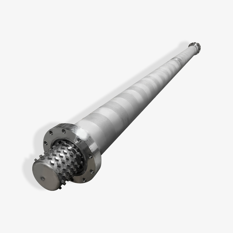
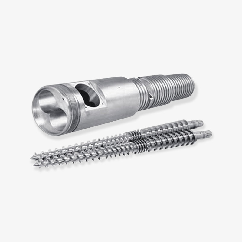
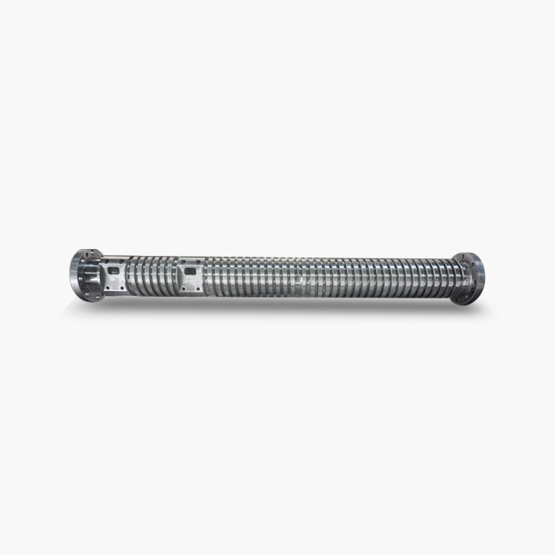 Custom Single Screw Barrel for ExtrusionCustom single screw barrel for extrusion with modular components and control support; relevant when feed-zone wear or screw-barrel clearance may affect conveying stability.View Product →
For extrusion lines, the same logic applies to the single-screw barrel and feeding sleeve. If the feed section is worn or the barrel-to-screw clearance is excessive, the conveying rate may become unstable. The additive injection system then receives a melt stream that is already varying in pressure and output. Calibration may still be possible, but it will require more frequent correction. A supplier that can discuss feed-zone design, compression ratio, and wear patterns is more useful than one that only quotes a part number.
Industrial buyers often compare a manufacturer, supplier, and wholesaler on lead time and unit price. Those factors matter, but they should be weighed with the cost of unstable production. A screw and barrel set that arrives with clear inspection data and a consistent material specification can reduce the number of variables during commissioning. That makes the first calibration faster and the long-term baseline more reliable. It also gives maintenance a reference point when wear eventually begins.
The best screw and barrel supplier reduces calibration variables by documenting dimensions, materials, and wear options before the parts reach the plant.
FAQ: Chemical Injection System Calibration and Testing
How often should a chemical injection system be calibrated?
There is no universal interval. A risk-based schedule is more useful: verify output at the production rate weekly, test low and high rates monthly or quarterly, and re-baseline after maintenance, material changes, or unexplained quality shifts. High-risk additives, abrasive fillers, and continuous lines usually need tighter checks than stable, low-risk applications.
What tolerance is reasonable for chemical injection system calibration?
The tolerance should come from the product requirement and the system capability. A common starting point is a narrow band around the target dose at the production rate, with separate checks at low and high rates. The record should state the target, the allowable deviation, the test rate, and the temperature so the result can be compared fairly.
Should calibration be done with water or with the production chemical?
Water is convenient for mechanical checks, but it may not represent the viscosity, density, or temperature sensitivity of the production chemical. Use water for initial leak and response checks when safe, then verify with a representative fluid or the actual chemical under controlled conditions. The correction factor should be based on the fluid that will run in production.
What tests should be repeated after replacing a screw or barrel?
Repeat the output test at multiple rates, the pressure-hold or leak check, the temperature soak verification, and a short production trial. A new screw or barrel can change pressure response, mixing, and residence time, so the old correction factor may no longer be valid. Re-baseline the system and record the new values.
How can I tell whether the dosing error comes from the pump or the screw and barrel?
Separate the system. Verify pump output by weight or volume at the injection point or a test port. Then check barrel pressure stability, screw recovery, check-ring sealing, and nozzle condition. If pump output is steady but product quality varies with pressure or cycle time, the melt-delivery hardware is the more likely source.
Does a bimetallic screw barrel eliminate calibration problems?
No. A bimetallic barrel can improve wear resistance in abrasive or corrosive applications, which may help the calibration baseline remain stable for longer. It does not replace output testing, pressure checks, temperature verification, or records. The metallurgy supports stability; the test plan proves it.
Why does additive dosing drift after a material lot change?
Material lots can differ in viscosity, filler content, moisture, or thermal behavior. Those differences change the melt pressure and the way the additive mixes. Recheck the production rate, temperature profile, and correction factor after a lot change. If the drift is large, verify that the additive itself has not changed in solids content or density.
Calibration and testing should answer three questions: what dose is delivered, what condition the machine is in, and what the product actually receives.
Final Commissioning Checklist for Stable Additive Injection
Before signing off a new or repaired system, confirm that the machine has reached thermal stability, the dosing lines are leak-free, the output has been checked at more than one rate, the pressure response is steady, and the production trial meets the quality requirement. Record the baseline in a form that the next shift can use. If a screw or barrel was replaced, note the new dimensions and material grade so future wear trends have a reference. If a new chemical lot is introduced, treat the first run as a verification run rather than assuming the old correction factor still applies.
The broader point is that calibration is a production discipline, not a maintenance formality. A chemical injection system can be technically calibrated and still produce bad parts if the melt-delivery hardware is unstable. It can also be mechanically sound and still drift if the test conditions are not representative. The plants that get the best results connect the dosing device, the screw and barrel, and the product quality check into one routine. They do not rely on a single number to prove that everything is under control.
That routine does not need to be complex. It needs to be repeatable, documented, and tied to the actual production condition. When that happens, calibration and testing become a tool for reducing scrap, protecting additive spend, and extending the working life of the screw and barrel. The result is a more predictable process, fewer emergency adjustments, and a clearer answer when something does drift.
Stable additive injection comes from a repeatable test routine that links the dosing device, the screw-barrel condition, and the final product result.
Selected Bearing Display


 浙公网安备33090202000520号
