


 English
 中文简体
中文简体
Author: WeiBo
Date: Aug 12, 2026
Screw Barrel and Screw Extruder: Types, Selection, and Maintenance Guide
Content
- 1 Understanding Screw Barrel and Screw Extruder Systems
- 2 Common Types of Screw Barrels and Their Characteristics
- 3 Core Structure and Working Principle of a Screw Extruder
- 4 Relative Wear-Resistance Comparison of Barrel Materials
- 5 Application Scenarios and Selection Criteria
- 6 Screw Speed and Output Rate: An Illustrative Relationship
- 7 Detailed Comparison: Single-Screw vs Twin-Screw Extruder Barrel Systems
- 8 Barrel Bore Diameter and Output Capacity Classes
- 9 Multi-Dimensional Performance Comparison of Barrel Materials
- 10 Maintenance Guidance for Screw Barrel and Screw Extruder Systems
- 11 Industry Trends and Manufacturing Practices in Screw Extrusion
- 12 Frequently Asked Questions About Screw Barrels and Screw Extruders
- 12.1 Q1: What is the difference between a screw barrel and a screw extruder?
- 12.2 Q2: How do I know when a screw barrel needs to be replaced?
- 12.3 Q3: Can a bimetallic barrel be used for unfilled resin processing?
- 12.4 Q4: What is a vented barrel used for?
- 12.5 Q5: Should barrel diameter be chosen based on current output needs or future growth?
A screw barrel is the cylindrical, wear-resistant metal housing that surrounds the rotating screw inside a screw extruder, and matching the correct barrel material, bore geometry, and screw configuration to the polymer being processed is the single most influential factor in extrusion output consistency, melt quality, and long-term equipment service life. Buyers who treat the screw and barrel as a matched pair rather than two independent parts generally see steadier throughput, fewer unplanned stoppages, and a longer interval between bore reconditioning cycles.
This guide walks through the common types of screw barrels and screw extruders, how they are built and how they work, where each configuration fits best, how the main options compare on paper, and how to keep a barrel and screw system running well once it is installed. Practical selection factors, illustrative performance charts, and a maintenance checklist are included throughout, along with a short FAQ section addressing the questions that plastics processors, OEM integrators, and equipment buyers most often raise when sourcing a screw barrel manufacturer or screw extruder factory.
Understanding Screw Barrel and Screw Extruder Systems
A screw extruder is the machine, and the screw barrel is one of its two core working components, paired directly with the rotating screw. Plastic pellets or powder enter through the hopper, are carried forward by the screw flight along the inside wall of the barrel, and are progressively compressed, melted by friction and conduction heat, and pushed toward the die at the discharge end. The barrel bore has to hold tight dimensional tolerances against the screw outside diameter, because the clearance between the two surfaces directly affects mixing quality, back-pressure, and how much material leaks backward along the flight instead of moving forward.
Because the barrel bore is in constant sliding contact with moving polymer, and often with abrasive fillers, pigments, or corrosive additives mixed into that polymer, the inner surface experiences continuous mechanical wear and, in many formulations, chemical attack as well. This is why barrels are rarely made from plain, untreated steel for demanding production; most commercial units use a hardened, nitrided, or alloy-lined bore to slow down wear and extend the interval between overhauls. A screw extruder supplier typically offers several barrel constructions so the buyer can match bore hardness and corrosion resistance to the resin, filler content, and expected duty cycle of a specific production line.
Selecting a barrel is therefore not a standalone decision. The barrel's internal diameter, length-to-diameter (L/D) ratio, and heating and cooling zone layout all have to correspond with the screw's compression ratio, flight design, and root profile, and with the extruder's drive torque and gearbox rating. Buyers sourcing from a screw barrel supplier for a new line, or replacing a worn barrel on existing equipment, generally get better results when they specify the resin, expected output rate, and any fillers or regrind content up front, rather than asking only for a barrel that fits a given bore diameter.
Key takeaway: the screw and barrel function as one matched system, and selecting barrel material, bore tolerance, and zone layout around the actual resin and filler profile is what determines extrusion consistency and barrel service life, not the bore diameter alone.
Common Types of Screw Barrels and Their Characteristics
Most screw barrels supplied for plastic extrusion fall into a small number of construction families, distinguished mainly by the bore material and surface treatment. Nitrided alloy steel barrels use a chromium-molybdenum-aluminum steel substrate that is nitrided to form a hard surface layer, and they remain the most widely used option for general-purpose extrusion of unfilled or lightly filled polyolefins. Bimetallic barrels use a centrifugally cast wear-resistant alloy liner fused to a steel outer shell, giving noticeably higher resistance to both abrasion and corrosion, which makes them a common choice when processing glass-filled compounds, flame-retardant formulations, or PVC. Vented and grooved-feed barrels are structural variants built for specific process needs rather than different bore materials, and segmented barrels are the standard construction for twin-screw compounding lines.
| Barrel Type | Core Material / Treatment | Relative Wear & Corrosion Resistance | Typical Use Case |
|---|---|---|---|
| Carbon / Alloy Steel Barrel | Untreated or hardened alloy steel | Basic | Light-duty, low-filler general extrusion |
| Nitrided Alloy Steel Barrel | 38CrMoAlA-type steel, gas nitrided bore | Moderate to good | General-purpose PE, PP, PS extrusion |
| Bimetallic Alloy-Lined Barrel | Centrifugally cast alloy liner over steel shell | High | Filled compounds, PVC, recycled/regrind streams |
| Vented Barrel | Nitrided or bimetallic, with degassing port | Depends on base construction | Moisture/volatile removal, PET and recycling lines |
| Segmented / Modular Barrel | Sectioned bimetallic or nitrided modules | High (module-dependent) | Twin-screw compounding, masterbatch production |
Grooved-feed barrels deserve a separate mention because they change how the extruder behaves rather than what it is made of. A grooved feed section increases the conveying efficiency of the solids in the feed zone, which raises the maximum achievable output and reduces the extruder's sensitivity to variations in bulk density, at the cost of a more complex feed-zone cooling requirement. Buyers evaluating a screw barrel manufacturer for a high-output single-screw line often ask specifically about grooved-feed options once their production targets exceed what a smooth-bore feed section can reliably deliver.
Core Structure and Working Principle of a Screw Extruder
Every single-screw extruder barrel is functionally divided into three zones along its length, even though the physical bore is a single continuous cylinder. The feed zone, nearest the hopper, is where solid pellets or powder first enter and begin to be conveyed forward by the deep flight channels. The compression zone gradually reduces the channel depth, compacting the material, forcing out trapped air, and beginning the melting process through a combination of barrel heater conduction and mechanical shear. The metering zone, nearest the die, has the shallowest and most consistent channel depth, and its job is to deliver a uniform, fully melted, pressure-stabilized flow to the die head.
Structural Diagram of a Typical Screw Barrel Assembly
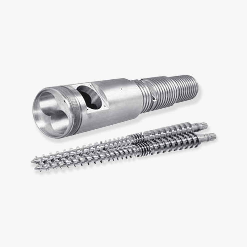
The schematic below lays out these zones along the barrel body, together with the surrounding heater bands, the internal screw visible through a cutaway section, and the thermocouple ports used for zone temperature control. Reading it left to right follows the same direction that the polymer travels during processing, from hopper intake through to the die adapter. The relative length of each zone shown here is illustrative rather than fixed, since actual zone proportions are adjusted by the screw designer to suit the resin's melting behavior.
Two dimensional ratios describe most of a screw extruder's processing character. The L/D ratio, the working length of the barrel bore divided by its diameter, commonly falls between 20:1 and 36:1 for single-screw extruders, with longer ratios generally giving better melt homogeneity and more stable output at the cost of a longer, heavier machine. The compression ratio, the feed-zone channel depth divided by the metering-zone channel depth, is typically set somewhere between 2:1 and 4:1 depending on how easily the resin melts and how much it needs to be compacted to remove entrained air. Neither ratio is fixed by the barrel alone; both are a joint outcome of the barrel's zone layout and the screw's flight geometry, which is another reason the two components are specified together rather than independently.
Relative Wear-Resistance Comparison of Barrel Materials
Bore wear is the single largest driver of barrel replacement cost over the life of a production line, so material selection is worth examining closely before ordering. The chart below presents an illustrative relative wear-resistance ranking across five common barrel constructions, scored on a simple ten-point scale for comparison purposes rather than as a precise laboratory measurement. This kind of ranking reflects the general ordering that plastics processing engineers commonly reference when discussing bore materials, from basic carbon steel through to advanced ceramic-composite and tungsten-carbide-particle linings. It is intended to help a buyer reason about trade-offs, not to substitute for testing against a specific formulation. Filler type, filler loading percentage, melt temperature, and screw rotation speed all shift where a given barrel construction would actually land on a real production line.
Reading the chart from top to bottom, carbon steel barrels sit at the lower end of the scale, which is consistent with why they are mainly recommended for light-duty applications processing unfilled resin with little to no regrind content. Nitrided alloy steel barrels roughly double the relative wear-resistance score, which explains their popularity as the default choice for general-purpose polyethylene and polypropylene extrusion where fillers are minimal. Bimetallic alloy-lined barrels show a clear step up again, and this is the category most frequently recommended once a formulation includes glass fiber, mineral filler, or corrosive flame-retardant packages. Tungsten-carbide-particle and ceramic-composite linings occupy the top of the scale and are generally reserved for the most abrasive or highest-throughput applications, such as heavily filled masterbatch compounding or continuous recycling of contaminated regrind streams.
It is worth noting that a higher wear-resistance score does not automatically make a barrel the right choice for every line; the decision also has to weigh how abrasive the actual material stream is, how many production hours per year the line runs, and how disruptive an unplanned barrel change-out would be to the operation. A processor running unfilled film-grade polyethylene on a single shift, for example, is unlikely to see a meaningful return from the highest-tier lining, while a compounding operation running 30 percent glass-filled nylon around the clock would typically wear through a basic carbon steel bore far faster than the production schedule can tolerate. This is why an experienced screw extruder factory will usually ask about filler content, regrind ratio, and expected annual run hours before recommending a specific barrel construction rather than defaulting to the highest-rated option in every quotation.
Application Scenarios and Selection Criteria
Screw barrels and screw extruders serve a wide range of downstream processes, and the right configuration depends heavily on what the line is actually producing. Pipe and profile extrusion generally favors a moderate L/D ratio with a nitrided or bimetallic barrel, since output stability matters more than aggressive mixing. Film blowing lines often specify a longer L/D ratio for better melt homogeneity, while compounding and masterbatch production almost always call for twin-screw segmented barrels because of the intensive dispersive and distributive mixing that formulation work requires. Wire and cable coating and recycling/reprocessing lines each bring their own filler, moisture, and contamination profiles that shape the barrel material decision independently of the base resin.
Typical Application IndustriesPipe and profile extrusion (PE, PP, PVC) Blown and cast film production Sheet and board extrusion Compounding and color masterbatch Wire and cable insulation coating Plastic recycling and regrind reprocessing |
Key Selection FactorsBase resin type and required melt temperature Filler or reinforcement content (glass, mineral, flame retardant) Regrind or contaminated feedstock ratio Target output rate and duty cycle (hours per day/year) Degassing or moisture removal requirements Compatibility with existing screw geometry and drive torque |
Common Barrel Configuration Options
Smooth-Bore Barrel
Standard feed section for general-purpose single-screw extrusion.Grooved-Feed Barrel
Higher conveying efficiency for high-output lines.Vented Barrel
Mid-barrel degassing port for moisture and volatiles.Segmented Barrel
Modular sections for twin-screw compounding lines.Bimetallic-Lined Barrel
Alloy liner for abrasive or corrosive formulations.
Key takeaway: selection should start from the material stream (resin, filler, regrind) and the required duty cycle, then work backward to bore construction and screw geometry, rather than starting from a bore diameter alone.
Screw Speed and Output Rate: An Illustrative Relationship
Throughput planning is one of the most common reasons buyers contact a screw extruder factory, and understanding how output responds to screw speed helps set realistic production expectations. The line chart below illustrates the general shape of this relationship for a typical single-screw extruder processing a standard polyolefin resin, plotting screw rotation speed in revolutions per minute against output rate in kilograms per hour. The curve is drawn from generalized extrusion engineering behavior rather than a specific machine model, and it is meant to show the pattern rather than exact figures for any particular barrel and screw combination. Two features of the curve matter most for planning purposes: the initial steep rise at lower speeds, and the flattening trend that appears as speed continues to increase. Actual figures for a specific line depend on barrel diameter, L/D ratio, screw design, resin melt index, and die restriction, so this chart should be read as a pattern rather than a specification.
In the lower speed range, roughly between 10 and 40 rpm on the illustrative curve, output rises quickly and almost linearly with each incremental increase in screw speed. This region is where most general-purpose extrusion lines are actually operated, because output is easy to predict and melt quality remains stable and easy to control at these speeds. As screw speed climbs past the midpoint of the curve, the rate of output gain per additional rpm starts to shrink, which reflects the growing influence of shear heating, melt viscosity changes, and die restriction on how much additional material the screw can actually convey. By the time the curve approaches its highest plotted speeds, output gains become quite small relative to the added rpm, illustrating a point of diminishing returns that many processors reach in practice.
This flattening pattern has practical consequences for production planning and for barrel selection. Pushing screw speed well past the point where output gains flatten out generally increases shear heating, energy consumption, and screw and barrel wear rate without a proportional increase in output, which is one reason many processors instead choose to increase barrel diameter or add a second extruder rather than continuously raising rpm on an existing line. It also explains why a grooved-feed barrel, discussed earlier in this guide, is often recommended specifically for operations that need to raise output substantially, since it shifts the entire curve upward rather than simply asking the existing smooth-bore feed section to run faster. Recognizing where a given line sits on this curve is a useful diagnostic when a processor is deciding whether a throughput shortfall should be solved by a barrel or screw redesign, or by a change in resin, die, or downstream equipment instead.
Detailed Comparison: Single-Screw vs Twin-Screw Extruder Barrel Systems
Single-screw and twin-screw extruders both rely on a matched screw and barrel assembly, but the barrels themselves differ significantly in construction and purpose. A single screw extruder barrel is a single continuous bore built for steady conveying, melting, and pressure generation, and it is the standard choice for pipe, profile, film, and sheet lines. A twin screw extruder barrel is almost always built as a figure-eight bore accommodating two intermeshing screws, and it is typically assembled from shorter modular segments so that the mixing configuration can be reconfigured for different formulations. The table below summarizes how the two systems compare across the factors that most often drive a buyer's decision.
| Factor | Single-Screw Barrel System | Twin-Screw Barrel System |
|---|---|---|
| Mixing Capability | Moderate, mainly distributive | High, dispersive and distributive |
| Structural Complexity | Simple, single bore | Higher, modular figure-eight bore |
| Feed Flexibility | Single main feed point | Multiple feed and side-feed ports |
| Typical Barrel Wear Profile | Gradual, whole-bore wear | Concentrated at kneading/mixing segments |
| Common Applications | Pipe, profile, film, sheet extrusion | Compounding, masterbatch, reactive extrusion |
The modular nature of twin-screw barrels is worth expanding on, since it is a frequent point of confusion for buyers new to compounding equipment. Because each barrel section can be swapped independently, a processor can reconfigure the mixing intensity of a line by changing which segments carry kneading blocks versus conveying elements, without replacing the entire barrel assembly. This also means wear tends to concentrate in specific high-shear segments rather than spreading evenly along the bore, so a well-run maintenance program for a twin-screw line typically tracks segment-level wear rather than treating the barrel as a single unit, which is a meaningfully different maintenance approach than the whole-bore inspection used on single-screw systems.
Barrel Bore Diameter and Output Capacity Classes
Bore diameter is the dimension most buyers start with when describing a screw extruder, so it is useful to see how it relates to approximate output capacity in practice. The column chart below groups five common single-screw barrel bore diameters against an illustrative midpoint output capacity class for each size, expressed in kilograms per hour under typical general-purpose processing conditions. These figures are presented as broad capacity classes rather than guaranteed output values, since actual throughput for any given bore size still depends heavily on L/D ratio, screw design, resin type, and die restriction, as discussed in the previous section. The pattern to notice is the relationship between bore size and capacity class, which is close to proportional to the cross-sectional area of the bore rather than to its diameter directly, meaning capacity increases faster than diameter as barrel size steps up.
Moving from a 45mm bore to a 65mm bore roughly doubles the illustrative output capacity class, while moving from 45mm all the way to 150mm increases it by more than tenfold, even though the diameter itself only grew about three and a half times. This non-linear relationship is a direct consequence of barrel cross-sectional area scaling with the square of the radius, and it is one of the main reasons that stepping up to the next standard bore size, rather than simply running an existing extruder faster, is often the more effective way to achieve a significant production increase. It also explains why a small increase in required output does not always justify a larger barrel purchase, since even a modest bore step-up can substantially overshoot a modest capacity target.
For buyers planning a new line or a capacity expansion, this chart is a useful starting point for sizing conversations with a screw barrel supplier, but it should be paired with the specific resin, screw design, and die restriction data for the actual product being run. Two extruders with the same bore diameter can have meaningfully different real-world output if their L/D ratios, compression ratios, or screw flight designs differ, which is why capacity classes like the ones shown here are best treated as a planning reference rather than a final specification. A detailed capacity study, ideally run against the actual resin and filler package intended for production, remains the most reliable way to confirm that a given bore size will meet a specific output target.
Multi-Dimensional Performance Comparison of Barrel Materials
Wear resistance is only one of several dimensions that matter when comparing barrel materials, so it helps to look at several performance factors side by side. The radar chart below compares carbon steel, nitrided alloy steel, and bimetallic alloy-lined barrels across five illustrative dimensions: wear resistance, corrosion resistance, cost efficiency, maintenance ease, and thermal stability, each scored on a ten-point scale. A larger enclosed area generally indicates a barrel construction with fewer trade-offs across these dimensions, while a narrow or lopsided shape indicates a construction that performs strongly in some areas and weakly in others. This kind of multi-factor view is particularly useful because the single highest-wear-resistance option is not automatically the best overall fit for every operation, as the earlier wear-resistance chart already suggested. Reading the three overlaid shapes together highlights where each material family's strengths and weaknesses actually sit.
■ Carbon Steel ■ Nitrided Alloy Steel ■ Bimetallic Alloy-Lined
Carbon steel barrels, shown as the smallest and most compact shape, score reasonably well on cost efficiency but fall noticeably short on both wear resistance and corrosion resistance, which is consistent with their positioning as an entry-level option for light-duty, unfilled resin processing. Nitrided alloy steel barrels form a more balanced shape, with moderate scores across all five dimensions rather than a sharp peak in any single one, which explains why this construction remains the default recommendation for general-purpose extrusion where no single performance factor is extreme. Bimetallic alloy-lined barrels show the most pronounced peak on wear resistance and corrosion resistance, extending furthest along those two axes, while pulling back somewhat on cost efficiency, reflecting the more involved manufacturing process needed to bond a wear-resistant alloy liner to a steel shell.
Thermal stability and maintenance ease tell a related story: nitrided barrels and bimetallic barrels both score close together on thermal stability, since both constructions handle standard processing temperature ranges without difficulty, but bimetallic barrels edge ahead on maintenance ease in this illustrative comparison because their alloy liner resists scoring and pitting that would otherwise require more frequent bore polishing or chrome replating. Taken together, the radar comparison reinforces a theme that runs through this entire guide: barrel material selection is a balancing exercise across several performance dimensions rather than a search for a single best material, and the right balance point shifts depending on the resin, filler content, and production schedule of the specific line in question.
Maintenance Guidance for Screw Barrel and Screw Extruder Systems
Barrel bore wear is progressive, and how a line is started up, run, and shut down has a measurable effect on how quickly that wear accumulates. Following a consistent maintenance routine is generally the most cost-effective way to extend barrel and screw service life, and most of the practices below apply to both single-screw and twin-screw systems, with segment-level inspection added for modular twin-screw barrels.
- Ramp barrel heating gradually during startup and allow full soak time before engaging the screw, since introducing mechanical load into a barrel that has not reached uniform temperature can cause uneven thermal expansion and increased friction.
- Avoid running the screw dry, meaning without material present in the bore, even briefly, because metal-to-metal contact between screw flight and barrel wall accelerates bore wear far faster than normal material-cushioned operation.
- Use an appropriate purging compound when switching between resins or colors, particularly when moving from a heavily filled or corrosive formulation to a cleaner one, to reduce residual abrasive or chemical contact with the bore surface.
- Check heater band and thermocouple calibration on a routine schedule, since inaccurate zone temperature readings can lead to localized overheating or under-melting that increases screw torque and bore friction.
- Monitor drive motor amperage draw over time as an early indicator of increasing friction from bore wear, since a gradual upward trend at constant screw speed and resin often signals growing clearance between screw and barrel.
- Measure bore diameter periodically at several points along the barrel length using an internal bore gauge, and track the readings over time to plan barrel replacement proactively rather than reactively.
- Keep the feed throat cooling system functioning correctly, since inadequate feed-zone cooling can cause premature softening of pellets before they reach the compression zone, leading to bridging and inconsistent conveying.
- For twin-screw systems, inspect individual barrel segments separately, since wear typically concentrates at kneading and mixing zones rather than spreading evenly across the full modular assembly.
Key takeaway: most barrel wear that leads to unplanned downtime is gradual and measurable in advance, so a routine inspection and amperage-tracking program is usually more cost-effective than reacting to output problems after they appear.
Industry Trends and Manufacturing Practices in Screw Extrusion
Demand for wear-resistant barrel constructions has generally trended upward across the plastics processing industry as more production lines incorporate recycled content, mineral fillers, and flame-retardant additives into their formulations, all of which increase abrasive or corrosive load on the bore surface compared with unfilled virgin resin. This shift has pushed bimetallic and modular twin-screw barrel options from a specialty request toward a more standard line item in many equipment quotations, particularly for processors handling recycling streams or engineering compounds. At the same time, buyers continue to expect barrels and screws to be engineered as a matched pair rather than purchased as generic replacement parts, which has encouraged closer collaboration between processors and their screw extruder factory partners during the specification stage of a new line or a barrel replacement project.
Manufacturers such as Zhoushan Microwave Screw Machinery Co., Ltd., a China-based screw barrel manufacturer and screw extruder factory, illustrate how this kind of specification-first approach has developed over time within the industry. The company has been engaged in the production and research of plastic machinery since it was founded in 1990, combining imported screw machinery technology with ongoing in-house development work. Its production operation spans more than 10,000 square meters of workshop space and is supported by a team of more than 60 employees, a scale that is broadly representative of established plastic machinery producers serving both domestic processors and export customers as a screw barrel supplier and screw barrel wholesaler. This kind of long-running, specialization-focused manufacturing background is generally a useful reference point for buyers comparing potential suppliers, alongside the technical selection factors covered earlier in this guide.
Looking ahead, several practical trends are worth watching for processors and equipment buyers. Interest in energy-efficient barrel heating and insulation continues to grow, since barrel heater bands represent a significant share of an extrusion line's electrical load, and better insulation and zone control can meaningfully reduce standby energy consumption without changing barrel material at all. Condition-monitoring instrumentation, including more granular thermocouple placement and amperage trend logging, is also becoming more common on new lines, supporting the kind of proactive maintenance approach described in the previous section. Processors evaluating a plastic extrusion machinery manufacturer for a new project increasingly ask about these monitoring and efficiency features alongside the traditional questions about bore material and output capacity, reflecting a broader shift toward treating the barrel and screw system as a data source for process optimization rather than a purely mechanical component.
Frequently Asked Questions About Screw Barrels and Screw Extruders
Q1: What is the difference between a screw barrel and a screw extruder?A screw extruder is the complete machine, including the drive motor, gearbox, heating and cooling system, and die head. The screw barrel is one specific component within that machine, the cylindrical bore that houses the rotating screw and guides material from the feed zone through to the die. |
Q2: How do I know when a screw barrel needs to be replaced?Common indicators include a gradual rise in drive motor amperage at the same screw speed and resin, a decline in output rate or increase in output variability, and bore diameter measurements that exceed the manufacturer's recommended wear tolerance when checked with an internal bore gauge. |
Q3: Can a bimetallic barrel be used for unfilled resin processing?Yes, a bimetallic barrel is compatible with unfilled resin processing and will typically last longer than a nitrided barrel under the same conditions. Whether the added wear resistance is necessary for a specific unfilled-resin line depends on run hours and duty cycle, which is best discussed directly with a screw barrel manufacturer during specification. |
Q4: What is a vented barrel used for?A vented barrel includes a degassing port partway along its length, allowing moisture and volatile byproducts to escape during processing. It is commonly used in recycling and reprocessing lines, as well as in processing resins such as PET that are sensitive to residual moisture during melting. |
Q5: Should barrel diameter be chosen based on current output needs or future growth?Because output capacity scales with bore cross-sectional area rather than diameter alone, even a modest increase in bore size can substantially exceed current needs. Many processors work with their screw extruder supplier to model both current and anticipated output requirements before finalizing bore diameter, rather than sizing strictly for present-day production volume. |
Selected Bearing Display


 浙公网安备33090202000520号