


 English
 中文简体
中文简体
Author: WeiBo
Date: Sep 01, 2026
What Is an Extruder? Definition, How It Works, Types, and a Buyer's Guide
Content
- 1 How Do Engineers Define an Extruder?
- 2 The Anatomy of an Extruder: The Parts That Do the Work
- 3 How an Extruder Works, Stage by Stage
- 4 Main Types of Extruders and Where Each One Fits
- 5 Screw and Barrel Configurations Worth Knowing Before You Buy
- 6 What Extruders Make: Applications Across Materials
- 7 The Word Extruder in 3D Printing
- 8 Buying an Extruder or Its Core Parts: What to Define First
- 9 Wear, Maintenance and Service Life of Screws and Barrels
- 10 Frequently Asked Questions About Extruders
- 10.1 How do you define an extruder in simple terms?
- 10.2 Is an extruder the same as an injection molding machine?
- 10.3 Should I choose a single screw or a twin screw extruder?
- 10.4 Why do screws and barrels wear out, and when should they be replaced?
- 10.5 Can one extruder run different polymers?
- 10.6 What should I check when choosing a screw and barrel manufacturer or supplier?
- 11 Related Extruder Resources
Any purchasing manager who has sent out a request for quotation for an extrusion line knows the routine: before a serious supplier quotes a price, the supplier asks three questions back. What material will you run? What output do you need, in kilograms per hour? And which die, or which finished product, will the machine feed? Those questions exist because an extruder is not one standardized product. It is a matched system built around a screw, a barrel and a die, and every commercial answer depends on how those three are defined.
Defined in one sentence: an extruder is a machine that continuously converts raw material into a uniform, pressurized melt and forces it through a shaped die to form a product of constant cross-section, such as pipe, sheet, film, profile, pellets or a coating layer. The word comes from the Latin extrudere, to thrust out, which is precisely what the rotating screw does to material inside a heated barrel. This guide defines the term the way plastics and rubber engineers actually use it, walks through the components and the process stage by stage, compares the main machine types with their typical dimensions, and closes with the buying and maintenance questions we answer every day as a screw and barrel manufacturer working with extruder OEMs and end users.
Key point: an extruder is defined by what it continuously does, meaning convey, melt, mix, pressurize and shape material through a die, not by any single part or brand name.
How Do Engineers Define an Extruder?
General dictionaries keep the definition broad: an extruder is something that extrudes, specifically a machine that shapes material by forcing it through a shaped opening. Industrial practice narrows that considerably. In plastics and rubber processing, an extruder is defined as a thermal processing machine in which one or more rotating screws turn inside a heated barrel to convey, melt, mix and pressurize polymer, and then pump it through a die at a controlled, continuous rate.
When engineers define extruder capability in a specification, they use four measurable terms. Output rate, quoted in kilograms per hour, states how much material the machine delivers. Melt quality covers temperature uniformity, additive dispersion and the absence of unmelted particles. Head pressure states the force available to push melt through screens, adaptors and dies. Specific energy consumption, in kilowatt-hours per kilogram, states how efficiently the machine delivers the first three. A supplier who cannot discuss these four numbers is selling a catalog page, not an extruder.
It also pays to separate the machine from the process. Extrusion is the process; the extruder is the machine that performs it. The distinction matters commercially because two extruders with identical rated output can behave very differently in production if the screw geometry, barrel material and temperature control are not matched to the polymer. Buyers who understand this evaluate the core components as carefully as the finished machine.
One more boundary is worth drawing. Injection molding machines contain a reciprocating screw that plasticizes material much like an extruder does, but an injection machine works intermittently: it meters a shot, injects it into a closed mold, holds it under pressure and cools it, then repeats. An extruder works continuously against a die, hour after hour. The two technologies share screw and barrel technology, which is why a manufacturer of extruder components usually serves the injection molding industry from the same production floor.
Key point: in industry an extruder is defined by continuous, measurable performance covering output, melt quality, head pressure and energy efficiency, rather than by the broad dictionary meaning.
The Anatomy of an Extruder: The Parts That Do the Work
Strip any extruder down to its essentials and two components carry nearly the entire processing load: the screw and the barrel. They operate as a matched pair, and their geometry, materials and running clearance decide most of what a buyer will feel in daily production, from output stability to service life. Everything else on the machine exists to power, feed, heat, cool or instrument that pair. The two panels below summarize each half of the partnership the way we discuss it with customers.
The screw: the rotating heartThe screw is the rotating, flighted shaft that does the mechanical work. Its channel is deliberately deeper at the feed end and shallower toward the discharge, creating the feed, compression and metering zones that convey, melt and pump. Key specifications include diameter, length-to-diameter ratio, compression ratio and any barrier or mixing sections. Screws are machined from alloy steel and hardened by nitriding or protected with bimetallic surfacing, because the wrong metallurgy turns a good design into a short-lived one. Serious suppliers design screw geometry around the specific polymer, filler content and head pressure of each application. |
The barrel: the pressure vessel around itThe barrel is the stationary cylinder wrapped around the screw, and it is far more than a pipe. Its bore is the wear surface that the flight tips run against, so it is either nitrided alloy steel or lined with a centrifugally cast bimetallic alloy for abrasive formulations. Heater bands are clamped around it in controlled zones, cooling is arranged where heat must be removed, and the feed pocket at the intake end is water cooled to keep material conveying instead of melting early. Barrel condition and bore clearance effectively set the ceiling on an extruder's efficiency. |
Around that central pair, a complete extruder adds the systems that make continuous production possible:
- Hopper and feed throat, which meter pellets, powder or regrind into the screw channel, with a cooled feed throat to prevent bridging.
- Drive system, typically a main motor and gearbox sized for torque at low screw speed, with a thrust bearing assembly that absorbs the axial load created by head pressure.
- Heating and cooling zones, with band or cast-in heaters and fans or blowers, each controlled independently along the barrel.
- Breaker plate and screen pack, which filter contaminants out of the melt, build uniform back pressure and protect the die.
- Die head and adaptor, which give the melt its final cross-section, whether that is a pipe head, a profile die, a sheet lip or a pelletizing plate.
- Instrumentation and controls, tracking zone temperatures, screw speed, melt pressure and melt temperature so operators can hold the process steady.
Key point: the screw and barrel work as one matched processing unit, so they should be specified, purchased and replaced together with compatible geometry and metallurgy.
How an Extruder Works, Stage by Stage
The quiet genius of an extruder is that a single rotating part performs conveying, melting, mixing and pumping in one continuous motion, with no reciprocating action and no batch cycles. Engineers divide the screw channel into functional stages to describe it, and every stage has a direct effect on what the buyer sees at the die.
- Solids conveying. Pellets or powder are fed into the screw channel and carried forward by friction against the barrel wall; grooved feed sleeves raise conveying efficiency for slippery materials such as HDPE.
- Delay and preheating. Heat conducted inward from the barrel softens the outer surface of the solid bed while the channel is still mostly full of solid material.
- Melting. A thin melt film forms at the barrel wall and is scraped into a melt pool by the advancing flight; shear from the rotating screw supplies most of the melting energy at production speeds.
- Compression and homogenization. Channel depth decreases, the growing melt pool squeezes the solid bed, trapped air escapes backward, and pressure climbs steeply; vented designs release volatiles here in a decompression zone.
- Metering and pumping. A shallow final section homogenizes the melt and delivers it at steady pressure and temperature, smoothing out upstream fluctuations before the die.
- Die forming and calibration. The melt crosses the breaker plate and die, takes the die's cross-section, and is then sized and cooled downstream by vacuum sleeves, calibrators, air rings or water baths.
Pressure tells the story of the whole machine. It is close to atmospheric at the hopper, climbs through the compression section and peaks just before the die, where screen pack and die resistance push back against the screw. A stable process is one in which the metering zone delivers melt at constant pressure and temperature, because everything downstream, from vacuum calibration on a pipe line to gauge control on a film line, depends on that consistency.
Where does the heat that melts the polymer actually come from? New buyers often assume the band heaters do all the work, because they are the parts you can see clamped along the barrel. In reality, the drive motor contributes most of the melting energy through viscous shear, as friction between the solid bed, the barrel wall and the melt converts mechanical power into heat. The split between external heating and internal shear generation changes with screw speed, material and machine size. The ring below shows the balance commonly observed on a mid-size single screw extruder running at typical production speeds, with the figures given as an illustration rather than a fixed specification.
Where the melting energy comes from in a typical single screw extruder
Mechanical shear from the drive (motor work)
External barrel heaters
Schematic split for illustration; the balance shifts with screw speed, material and machine size.
The ring above carries a message that surprises many first-time buyers: at production speed, the extruder largely heats itself. The motor's mechanical work is converted into heat by shear between the solid bed, the melt and the barrel wall, so the drive system is as much a heating device as the heater bands. Several practical consequences follow. First, temperature zones must be tuned as a balance, because heaters running at full output usually indicate a screw that is not generating enough shear, while zones demanding constant cooling indicate too much. Second, melt temperature measured at the adaptor is a better indicator of real material condition than barrel setpoints. Third, shear-sensitive materials such as rigid PVC call for screw geometries and screw speeds chosen to limit viscous heating, which is one reason conical twin machines run at moderate speeds. Fourth, the heat balance explains why output changes with screw speed are not perfectly linear. Fifth, it explains efficiency differences between machines, since a worn screw and barrel with excessive clearance recycle melt internally and waste kilowatt-hours. Sixth, it explains why cooling of the feed throat is never optional, because melt forming there too early causes bridging and interrupts conveying. Seventh, it explains start-up procedure: zones are brought to temperature before screw rotation begins, so early shear does not act on cold, stiff polymer. Treat the heater bands as trim rather than as the main melting source, and many running problems become far easier to diagnose.
Key point: at production speed the extruder largely heats itself through mechanical shear, so screw geometry, drive sizing and temperature control must be engineered together as one heat balance.
Main Types of Extruders and Where Each One Fits
Extruder is a family name, and the differences between its members come down to three questions: how many screws turn, how they are arranged, and how much shear and residence time the design delivers. The types below are the ones most often quoted in plastics and rubber processing, each matched to the products it does best.
Single screw extruders
The single screw extruder is the workhorse of the industry and the machine most people picture when they hear the word. One flighted screw turns in a smooth or grooved barrel at a controlled speed, melting pre-compounded pellets and pumping them through the die. Its virtues are simplicity, robustness, lower purchase cost and easy maintenance, which is why it dominates pipe, sheet, film, profile and pelletizing lines built around uniform materials. A realistic span runs from a few kilograms per hour in laboratory machines to more than a thousand kilograms per hour in large-diameter units. Grooved feed sections, barrier screws and distributive mixing elements extend what a single screw can handle.
Conical twin screw extruders
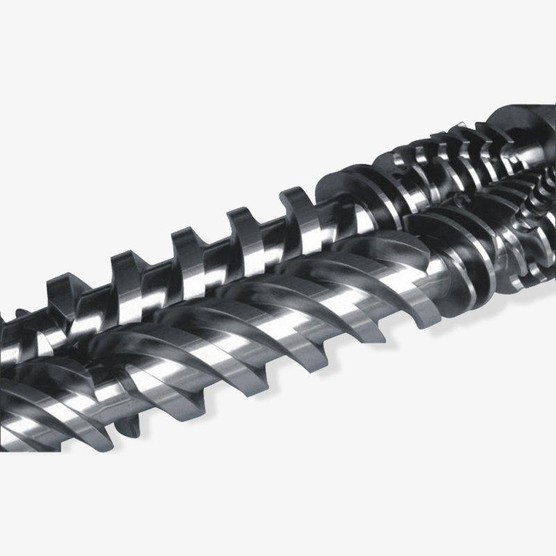
Conical twin screw extruders use two counter-rotating screws whose diameter tapers from a large feed end to a smaller discharge end. The taper is the design's signature: it provides deep, wide channels where powder must be grabbed and conveyed, then progressively compresses material as the channel narrows, all at modest screw speeds with high available torque. That combination makes conical twin machines the standard choice for extruding rigid PVC directly from dry powder blend into pipe, profile and board, with gentle shear that protects heat-sensitive formulations and stabilizer packages. Because the screws and barrels taper as matched pairs, replacement parts must be ordered as sets, which is precisely how we manufacture and supply them.
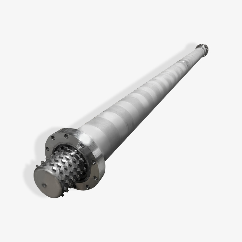
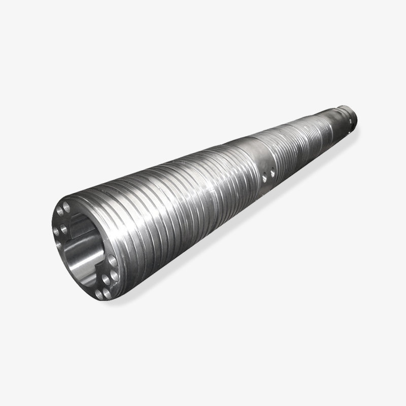
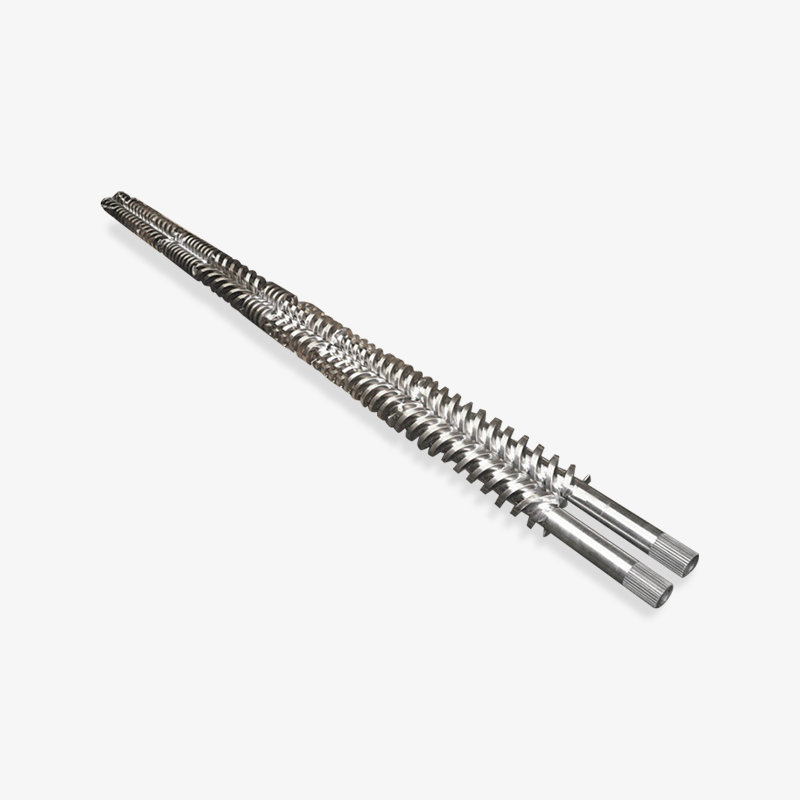
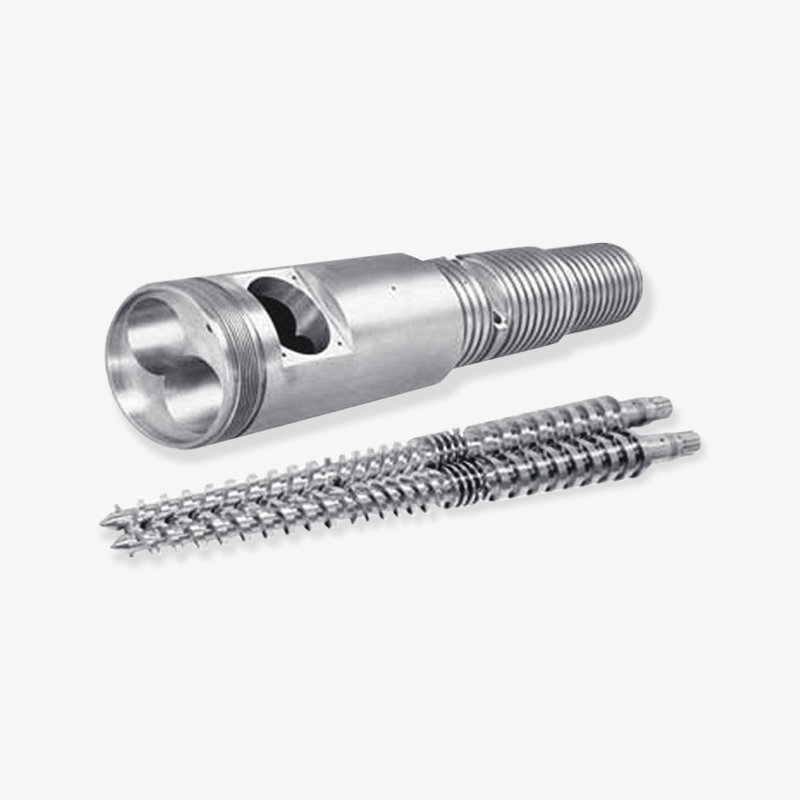
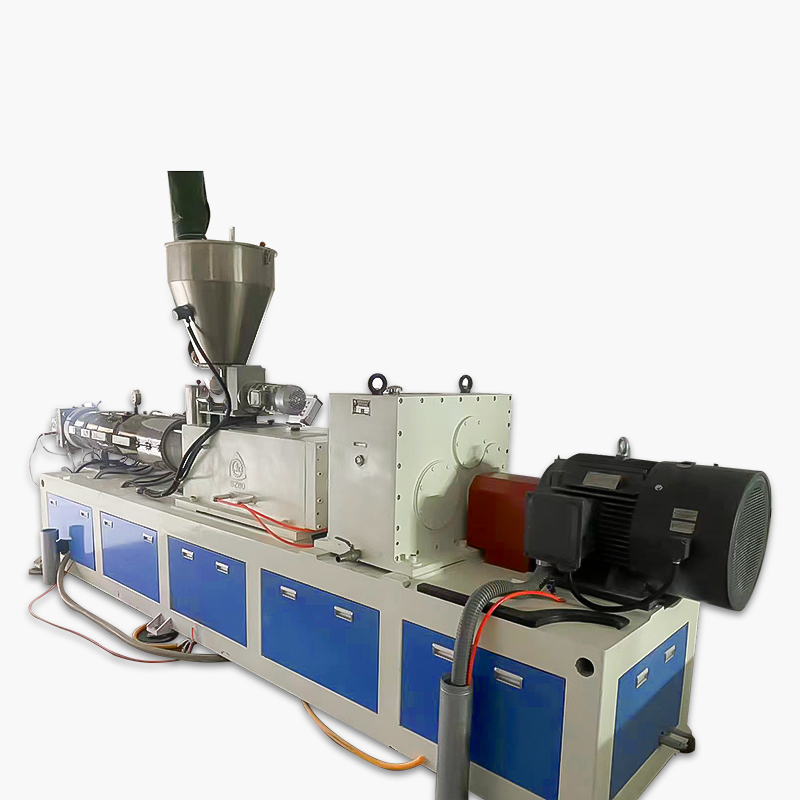 Conical Twin screw plastic extruderThe conical twin screw plastic extruder runs through the screw design, ensuring that the material is fully mixed and plasticized during the extrusion process, thereby ...View Product →
Parallel twin screw extruders
Parallel twin screw extruders keep the same diameter along the full screw length, which leaves room for long process sections and higher screw speeds. Counter-rotating parallel machines push rigid PVC extrusion to higher outputs than conical designs, while co-rotating parallel machines dominate compounding, masterbatch and engineering polymer blends, where modular screw elements can be rearranged to knead, disperse, devolatilize and build pressure. Long length-to-diameter ratios, sometimes beyond 40:1, are common because each process task needs its own section of screw.
Planetary screw extruders
In a planetary screw extruder, a main driving screw carries a ring of freely rotating planetary spindles that roll between the screw flights and a toothed barrel section. The concept trades screw length for surface area: material is spread into thin layers and continuously reworked, which produces intensive mixing, rapid devolatilization and excellent temperature control over a very short processing length. Calender feed for rigid PVC and other heat-sensitive compounds are classic applications, and the design is equally valued when formulations change frequently.
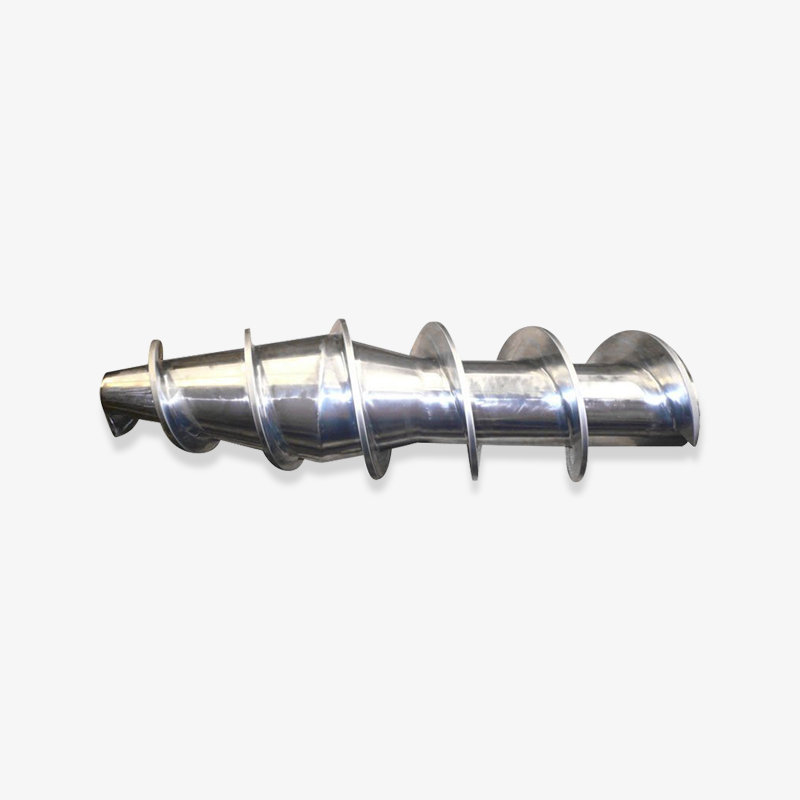
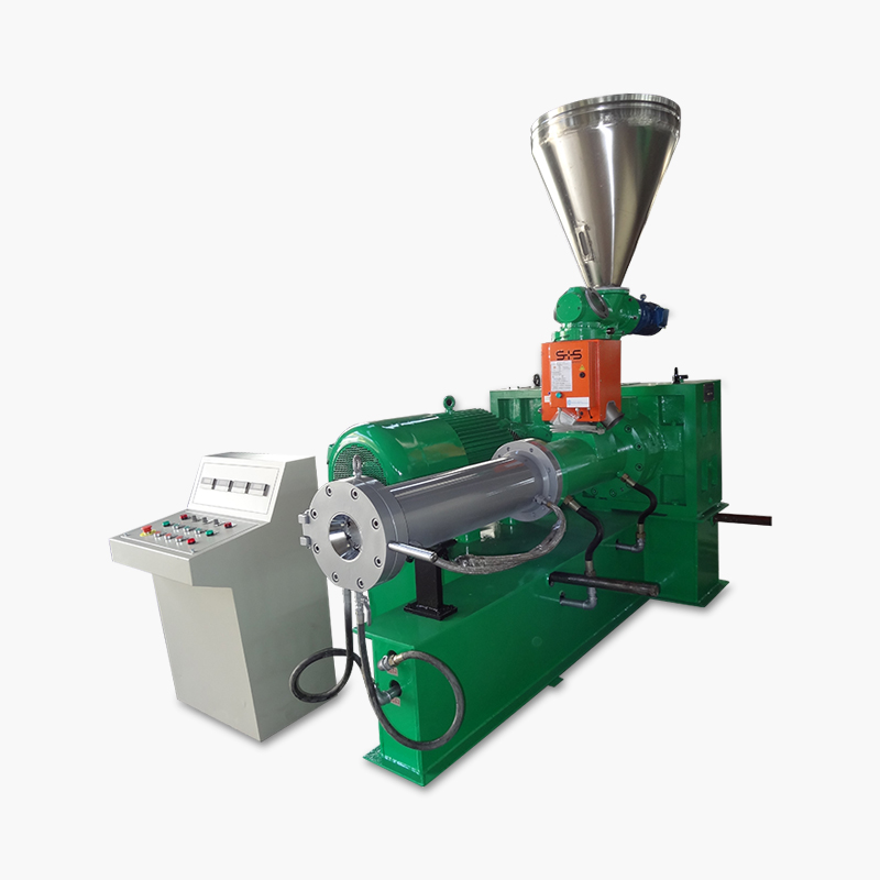 Planetary screw extruder for plastic processingThe planetary screw extruder is an advanced plastic processing equipment that is widely used in plastic product processing and food processing due to its unique planet...View Product →
Rubber and specialty extruders
Rubber extruders adapt the same principle to high-viscosity elastomer compounds, typically with deep channels, low screw speeds and either warm-feed or cold-feed configurations, producing profiles, hoses, cable covers and preforms. Beyond polymers, ram extruders push batch charges of PTFE paste, and the same extrusion principle shapes ceramics, food products and even aluminum. The word travels across industries because the underlying idea, forcing material through a shaped opening, is universal, even when the machinery shares nothing else.
| Type | Screw arrangement | Typical jobs | Practical strengths |
|---|---|---|---|
| Single screw | One flighted screw in a smooth or grooved barrel | Pipe, sheet, film and profile from pre-compounded pellets | Simple, robust, economical and easy to maintain |
| Conical twin screw | Two counter-rotating tapering screws | Rigid PVC pipe, profile and board from powder blends | Strong powder feeding, high torque at low speed, gentle shear |
| Parallel twin screw | Two parallel screws, counter-rotating or co-rotating | High-output PVC extrusion, compounding and masterbatch | Long processing section, high output, flexible configuration |
| Planetary screw | Main screw with orbiting planetary spindles | Calender feed and compounding of heat-sensitive compounds | Intensive mixing, large working surface, stable temperatures |
| Rubber extruder | Deep-channel single screw, warm feed or cold feed | Rubber profiles, hoses and cable covers | Handles high-viscosity compounds at controlled temperature |
Why the L/D ratio differs by design
Once buyers start comparing types, one specification repeats in every quotation: the L/D ratio, screw length divided by screw diameter. A longer screw provides residence time for melting, venting and homogenizing, while a shorter screw saves space, torque and cost. Each machine type has settled on a different customary range because each balances those demands differently. The bars below show the usual engineering ranges rather than absolute limits, and individual designs can extend beyond them. Read alongside the table above, the chart makes it obvious why a planetary machine looks so short while a compounding twin screw looks so long.
Typical screw L/D ratio ranges by extruder type
Customary engineering ranges for comparison; individual designs may extend beyond them.
Three patterns stand out in the chart. First, compounding-oriented parallel twin screws stretch toward 48:1 because mixing, filler dispersion, devolatilization and pressure build-up each demand their own section of screw length, which is also why modular element design matters so much on these machines. Second, conical twin screws achieve effective plasticizing within roughly 12:1 to 20:1 because the taper does much of the compression work geometrically, letting the machine feed powder reliably without a long metering section. Third, planetary designs sit at the very short end because their mixing intensity comes from rolling contact and surface renewal rather than from channel length. Standard single screws cluster around 20:1 to 30:1, long enough to melt and meter pre-compounded pellets yet short enough to keep cost and torque reasonable. When venting or devolatilization is required, single screws grow toward 28:1 to 36:1 to accommodate a second processing stage. Buyers should treat these ranges as a starting point for discussion, not as a rule. A proposed L/D far outside the customary band is a legitimate question to raise with the supplier, because it affects thrust load, residence time, shear history and ultimately price. The ratio also interacts with output, since higher throughput on the same diameter generally pushes designs toward longer screws. Finally, replacement parts are affected too, because a longer screw means more surface to harden, grind and inspect during refurbishment.
Key point: choose the extruder type from the material and the product first, and let the L/D ratio and screw geometry follow from that decision instead of comparing numbers in isolation.
Screw and Barrel Configurations Worth Knowing Before You Buy
Between a standard catalog machine and a fully custom line sits a set of proven configurations that account for most real quotations. Knowing the vocabulary makes offers easier to compare and helps a supplier propose the right hardware the first time. The cards below describe the configurations we most frequently combine on screws and barrels, and each one exists to solve a specific formulation or quality problem rather than to add cost for its own sake.
Smooth-bore barrel
The standard economical choice. It works well for most pellets, is the easiest to clean and inspect, and serves as the baseline against which every other option is compared.
Grooved feed section
Lengthwise grooves in the feed sleeve bite into slippery HDPE and PP, raising conveying efficiency and stabilizing output. It demands serious feed-pocket cooling and hard-wearing grooves.
Vented two-stage barrel
A decompression zone and vacuum port release moisture, volatiles and trapped air. Common for PET, ABS regrind and filled compounds where upstream drying is difficult.
Bimetallic barrel
The bore carries a centrifugally cast alloy liner with hardness far above nitrided steel. The default answer for glass-filled compounds and abrasive or corrosive formulations.
Nitrided screw and barrel
Gas nitriding hardens the surface of alloy steel at moderate cost. A sensible service-life upgrade over plain machined parts for general-purpose running.
Barrier and mixing screws
Barrier flights separate solids from melt so melting stays stable at high speed, while distributive and dispersive mixing sections finish the dispersion of color and fillers.
These options combine freely. A vented, grooved-feed single screw running glass-filled nylon on a bimetallic barrel is a normal specification in compounding plants, while a nitrided smooth-bore set remains the sensible choice for unfilled polyolefin pipe. The deciding factors are always the same: how abrasive the formulation is, how much moisture or volatiles it carries, and how shear sensitive the polymer is.
Key point: configuration choices such as grooved feed, venting, bimetallic lining and screw metallurgy should be driven by abrasiveness, moisture and shear sensitivity, not by habit or catalog defaults.
What Extruders Make: Applications Across Materials
The list of products that leave an extruder die is long, and it maps directly onto the machine types above. In plastics, extrusion lines produce pipe and fittings, window and door profiles, sheet for thermoforming, blown and cast film, wire and cable coating, and the compounding or pelletizing of colored, filled and recycled materials. Each product family stresses a different part of the machine: pipe lines emphasize steady head pressure, film lines emphasize melt temperature uniformity, and compounding lines emphasize mixing and wear resistance.
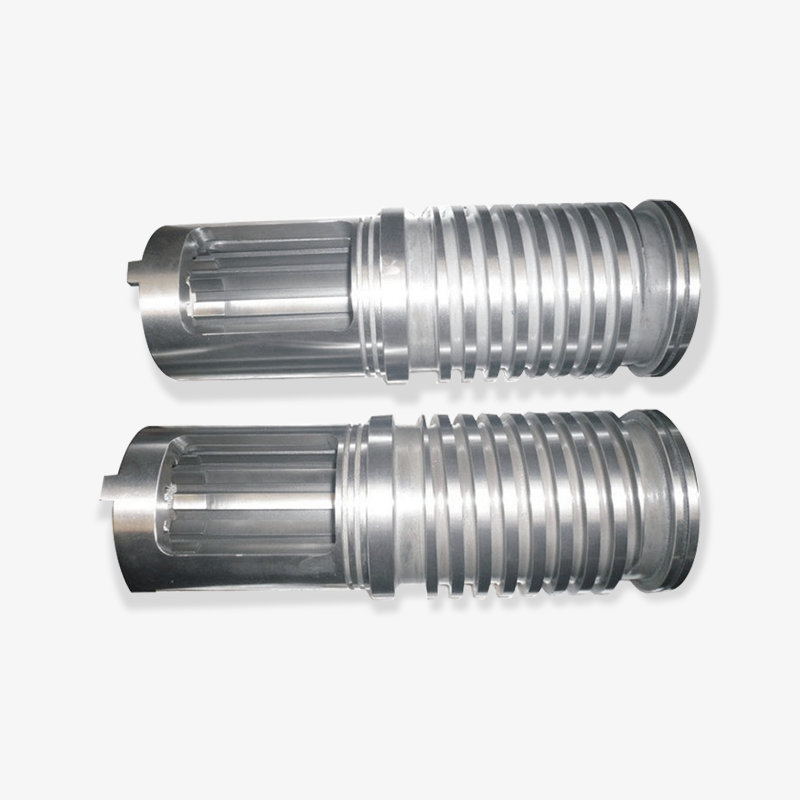
Foam extrusion deserves a special mention because it turns the machine inside out. In expanded polyethylene, or EPE, processing, the screw and barrel must handle polymer combined with a physical blowing agent, controlling nucleation and expansion with tight temperature discipline, and the screw geometry differs visibly from a standard conveying design. EPE foam logs are then slit and converted into packaging profiles, insulation and filling material, one of the most demanding niches in extrusion and one where barrel temperature zones and screw design decide product quality directly.
 EPE foam extrusion screw barrelThe EPE foam extrusion screw barrel is designed for efficient and stable production of high-quality EPE products. The barrel adopts advanced screw extrusion technology...View Product →
Rubber extrusion runs continuously as well, shaping construction and automotive seals, hoses and cable sheathing from high-viscosity compounds on dedicated rubber screws. And outside the polymer world, the same definition applies: extruders puff snack foods, form ceramic bricks and catalyst substrates, and press heated aluminum billets through profile dies. The word travels across industries because the principle of forcing material through a shaped opening is universal, even when the machinery shares nothing else.
Key point: from PVC pipe to EPE foam and rubber seals, the definition of the extruder stays the same, but every application demands its own screw geometry, barrel material and temperature profile.
The Word Extruder in 3D Printing
Search for the word extruder today and a very different machine appears next to the industrial one: the extruder of a filament 3D printer. In fused filament fabrication, the extruder is the module that grips the filament and feeds it toward the nozzle. It divides into a cold end, the motor-driven gears that push the filament, and a hot end, the heated block and nozzle that melt it. Direct-drive designs mount the gears directly above the hot end, while other designs push the filament through a short tube from a remotely mounted motor, a layout that trades responsiveness for a lighter print head.
The connection to industrial extrusion is real but easy to overstate. Both devices force molten material through a shaped opening, so the underlying principle is genuinely shared. The scale is not: a desktop extruder delivers grams per hour through a fraction-of-a-millimeter nozzle, while an industrial extruder delivers kilograms per hour through a machined die, with a screw and barrel doing the melting inside a controlled barrel. When buyers search for definitions, it helps to know which machine a page is describing, because the components, the suppliers and the purchasing logic are entirely different.
Key point: in 3D printing the extruder names a small filament-feeding module, while in industry it names the whole continuous machine; the shared idea is melt forced through a shaped opening.
Buying an Extruder or Its Core Parts: What to Define First
Most quotation delays trace back to missing definitions on the buyer's side, and most early failures trace back to shortcuts on the supplier's side. The two columns below summarize the conversation we try to have with every OEM and end user before numbers appear on an offer. They apply equally whether the purchase is a complete machine, a spare screw and barrel set, or a single component for an existing line.
Define before requesting a quotation
|
Verify before choosing a supplier
|
Supplier depth matters more in this industry than in most. A screw and barrel manufacturer founded in 1990 in Zhoushan, China, with more than 10,000 square meters of production space and a workforce of over 60 people, can machine planetary, conical twin, parallel twin and single screw sets, bimetallic components, injection molding machine screws and rubber extruder screws on the same floor, and can quote either single parts or complete sets. Export experience to markets such as the United States, Germany, Dubai, Vietnam and Thailand also says something practical: the supplier is used to documentation, packing and communication across borders. Whether you buy as an OEM, an end user or a wholesaler, that manufacturing depth is what turns a drawing into a working part.
Key point: define material, output and die first, then choose a supplier whose in-house screw and barrel manufacturing can document hardness, geometry and on-time delivery.
Wear, Maintenance and Service Life of Screws and Barrels
Wear in an extruder is not a defect; it is a predictable cost of doing work. Three mechanisms dominate. Abrasive wear comes from glass fiber, calcium carbonate and regrind scouring the flight tips and the bore. Adhesive wear appears when screw and barrel metal contact each other under high pressure and thin lubrication, often near the compression zone. Corrosive attack follows chemistries that release aggressive byproducts, as some PVC and fluoropolymer formulations do. The formulation chosen at the buying stage therefore writes most of the maintenance schedule in advance.
The symptoms of wear are consistent enough to teach any operator. Output drifts downward at constant screw speed. Melt temperature climbs because melt recirculates over worn flights instead of moving forward. Pressure becomes unstable, colors shift between batches, and dark specks appear where stagnant material sits in enlarged clearances. A planned inspection that measures bore diameter and flight outside diameter turns these observations into numbers, and comparing them with the original drawings shows exactly how much life remains in the set.
When the numbers cross the practical limit, the decision is rebuild or replace. Flight surfaces can sometimes be reclaimed and re-ground, and a worn nitrided barrel can be replaced by a bimetallic one as an upgrade rather than a like-for-like swap. Because screw and barrel wear as a pair, sound practice is to replace them as a matched set with clearance restored to specification, and to keep a spare set for critical lines so a wear event becomes a scheduled changeover instead of unplanned downtime. Daily habits matter as well: never start the screw on a cold barrel, purge correctly at shutdown, keep screen packs changed on schedule, and trend melt pressure so wear is seen coming rather than discovered.
Key point: wear is measurable and predictable, so track output, pressure and clearance, and plan screw and barrel replacement as scheduled maintenance rather than an emergency.
Frequently Asked Questions About Extruders
How do you define an extruder in simple terms?
An extruder is a machine that takes raw material, melts and pressurizes it with a rotating screw inside a heated barrel, and pushes it through a shaped die to form a continuous product such as pipe, film, sheet or pellets. The process is continuous, and the machine is built around the screw and barrel pair that does the conveying, melting and pumping.
Is an extruder the same as an injection molding machine?
No. An injection molding machine plasticizes material with a screw and then injects discrete shots into a closed mold, cycling between metering, injection, packing and cooling. An extruder runs continuously against a die. The two technologies share screw and barrel design, so components for both often come from the same manufacturer.
Should I choose a single screw or a twin screw extruder?
Start from the material and the product. Pre-compounded pellets shaped into pipe, sheet or film usually run best and most economically on a single screw. PVC powder, high-fill formulations and compounding tasks favor twin screw designs: conical twin machines for rigid PVC profiles and pipe from powder, and parallel twin machines for higher output and compounding work.
Why do screws and barrels wear out, and when should they be replaced?
Three mechanisms dominate: abrasion from fillers and regrind, adhesive wear from metal contact under high pressure, and corrosion from certain chemistries. Watch for falling output at constant screw speed, rising melt temperature and unstable pressure. When bore-to-flight clearance exceeds workable limits, rebuild or replace the screw and barrel as a matched set to restore the designed clearance.
Can one extruder run different polymers?
Within limits. A general-purpose screw tolerates a family of similar materials, but output and melt quality suffer when geometry, compression ratio and L/D ratio do not suit the polymer. Operations that switch between very different materials usually order dedicated screw and barrel sets for each, which costs less than the scrap and downtime of a mismatched process.
What should I check when choosing a screw and barrel manufacturer or supplier?
Look for in-house machining, heat treatment such as nitriding, and bimetallic casting capability; documented material and hardness certificates; design support for custom geometry; and export experience with spare parts service. A supplier who can produce single components and complete sets will also support you better across the whole life of the machine.
Key point: most extruder questions resolve back to the same trio of material, product and wear strategy, so answer those three before comparing prices.
Related Extruder Resources
The topics above only scratch the surface of extruder engineering. For readers planning a purchase, a rebuild or a spare parts program, two resources from our site go deeper: the company and product overview behind the screws, barrels and machines mentioned throughout this guide, and a technical article on the parallel twin screw technology described in the types section.
- Zhoushan Microwave Screw Machinery Co., Ltd.: company overview and the full screw, barrel and extruder product range
- How parallel twin screw technology achieves efficient material mixing, conveying and processing
Key point: the product pages and technical articles behind these links extend everything above, from screw geometry to complete extruder supply.
Defined plainly, an extruder is a continuous melting and shaping machine, and its real personality lives in the screw and barrel pair at its core. Buyers who hold on to that fact make better choices at every step: they compare machines by processing capability, specify components to match their formulation, and treat wear as a planned cost instead of a surprise.
If you are defining an extruder project right now, whether a new line, a rebuild or a spare set of screws and barrels, our engineering team can turn your material, output and die data into a concrete specification, from drawing to delivery. That is the work we have done since 1990 for extruder OEMs and plastics factories on several continents, and it remains the shortest path from the definition above to a machine that earns its keep.
Key point: the definition is simple, but the specification is where value is created; bring material, output and die data to the conversation and the right extruder follows.
Selected Bearing Display


 浙公网安备33090202000520号